8-bit CPU control signal overview
2017-04-15
[public] 153K views, 4.20K likes, 8.00 dislikes audio only
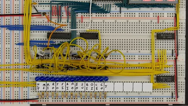
This video goes over the control signals used in our 8-bit breadboard computer.
Support me on Patreon: https://www.patreon.com/beneater
See https://eater.net/bbcpu8-bus for more.
Additional components used in this video:
- 15x LEDs to indicate which control signals are active
- 15x 470Ω resistors for the control signal LEDs
- 15x 470Ω resistors for the bus LEDs
- 2x 74LS04 Hex inverter (optional, but makes the control word simpler to interpret)
- Red gel (e.g., https://www.amazon.com/dp/B004GE19E2)
https://www.patreon.com/beneater
Building control logic
/youtube/video/AwUirxi9eBg?t=104
/youtube/video/AwUirxi9eBg?t=104
Memory in signal
/youtube/video/AwUirxi9eBg?t=175
/youtube/video/AwUirxi9eBg?t=175
RAM in signal
/youtube/video/AwUirxi9eBg?t=293
/youtube/video/AwUirxi9eBg?t=293
Instruction register in signal
/youtube/video/AwUirxi9eBg?t=361
/youtube/video/AwUirxi9eBg?t=361
Subtract signal
/youtube/video/AwUirxi9eBg?t=419
/youtube/video/AwUirxi9eBg?t=419
Output signal
/youtube/video/AwUirxi9eBg?t=452
/youtube/video/AwUirxi9eBg?t=452
Program counter
/youtube/video/AwUirxi9eBg?t=490
/youtube/video/AwUirxi9eBg?t=490
Other changes
/youtube/video/AwUirxi9eBg?t=698
/youtube/video/AwUirxi9eBg?t=698
Red plastic
/youtube/video/AwUirxi9eBg?t=752
/youtube/video/AwUirxi9eBg?t=752
Ben Eater Subscribe to see tutorial-style videos about electronics, computer architecture, networking, and various other technical subjects. If you want to see more on a particular subject, leave a comment and I'll try my best to add more.
If you'd like to support my work, please do!
https://www.patreon.com/beneater
https://paypal.me/beneater
https://cash.me/$eater
bitcoin:1EaterJkmmuJWfm8hvULrMJGm7R8JgXTL8
bitcoincash:1JUjEErUjkgBVJP28GH6LKihvEUJ1RGZhx
/youtube/channel/UCS0N5baNlQWJCUrhCEo8WlA
/youtube/channel/UCS0N5baNlQWJCUrhCEo8WlA
Building an 8-bit breadboard computer! by Ben Eater
/youtube/video/HyznrdDSSGM
/youtube/video/HyznrdDSSGM

