2024-10-26
[public] 78.8K views, 5.92K likes, dislikes audio only

Head to https://squarespace.com/hyperspacepirate to save 10% off your first purchase of a website or domain using code HYPERSPACEPIRATE
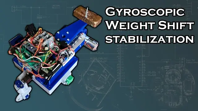
In this video I'll show how I improved my gyro stabilization system by switching from control-moment gyroscopes to a single passive gyroscope on a gimbal with weight shifting to develop stabilizing torque.
At rest, the gyroscope is laying flat, but the gimbal is free to rotate about the vehicle's pitch axis. This causes a torque that resists any changes in angle on the vehicle's roll axis, but by itself, isn't able to keep the vehicle upright indefinitely, but rather it serves as an extremely strong roll "damper".
By dramatically reducing the roll acceleration produced by a disturbing torque, the stabilizing gyroscope provides a large window of time for correcting the roll, meaning it can actually be stabilized with manual weight shifting - which i demonstrated in the first part of the video by rigging a large ballast weight on a lever to a remote controlled servo.
For automated stabilization, the system uses an MPU6050 gyro/accelerometer to provide tilt angle data to an arduino nano, which applies a correction with a weight-shifting servo proportional to the magnitude of the roll error. However, this alone won't keep the vehicle upright indefinitely, because in cases where large disturbances occur, the correction torque can cause the vehicle to build up enough angular momentum that it rolls itself to the opposite extreme before the weight shifter can respond.
To account for this scenario, a second input is provided to the feedback loop using the tilt angle of the passive gyroscope. The tilt angle is read by measuring the analog voltage output of a potentiometer connected to the gimbal shaft. This data could also come from the MPU6050 itself, but I thought it'd be interesting to use a direct analog measurement from a mechanical source.
The more tricky part of stabilizing the vehicle comes from turns when driving forward. These might actually require a separate control moment gyro for correcting the much larger but short-term accelerations.
The whole system is fed by either a 3S or 4S (12V or 16V) LiPo battery to a 620 kV brushless motor for the gyroscope and a 550 RPM dc gearmotor for the drive wheel. +5V DC is provided by an LM2596 buck converter module for the Arduino, RC Reciever, MPU6050 sensor, and servos. The gyroscope flywheel is a 80mm x 16mm brass disc.
With a little more development I'm confident that this approach can be used to make a full-scale bicycle self-balancing (and remote control).
Previous videos on Gyro stabilization:
Passive gyro - one wheel vehicle:
Control moment gyro stabilized monorail: